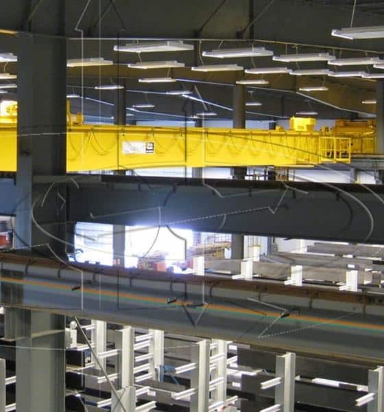
This tech bulletin is to provide insight and suggestions for applications using traditional variable frequency drives in a linear motion (Trolley or Bridge) application and have a requirement to operate that motion near mechanical stops.
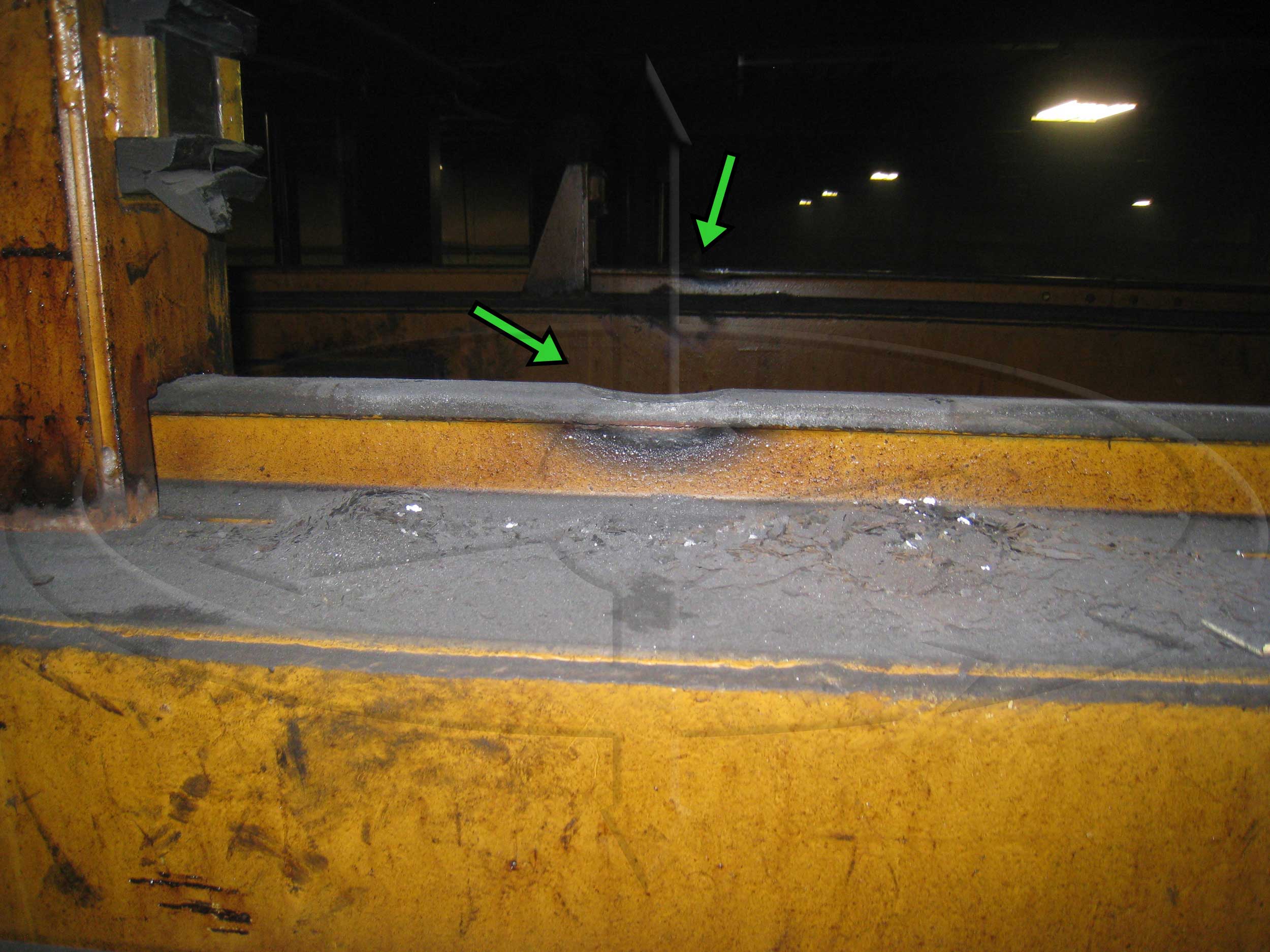
One look at the above picture and anyone familiar with overhead cranes will know that the trolley wheel has gouged out the trolley rail. In this case, the trolley motion was using a variable frequency drive control, and the plant production required the trolley to operate on a regular basis near or at the trolley stops.
The problem is that the variable frequency drive is programmed for a specific slowdown rate in seconds, and in a light or no load condition the trolley can be up against the stops, and the drive is still decelerating the motor to stop, causing the trolley drive wheel to continue to turn, but with nowhere to go. Making things worse, the operator sometimes tried going in the wrong direction with the trolley, again spinning the wheels and making metal.
The repair for a top running trolley can be pretty simple, but in an underhung application gouging like this can ruin a structural member with no chance of repair. In any case this type of damage and downtime can be avoided with simple travel limits.
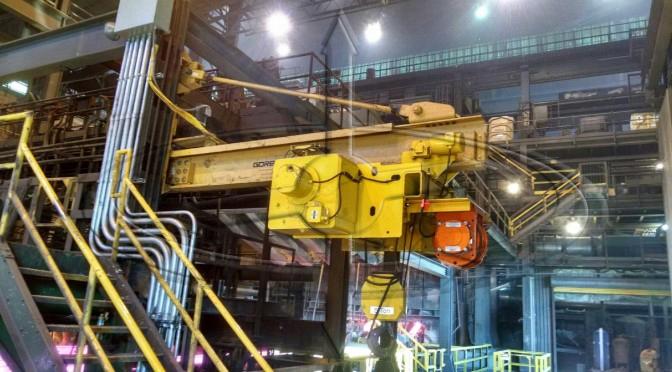
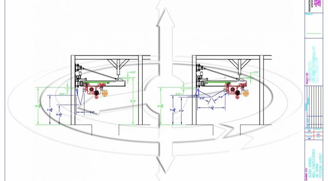
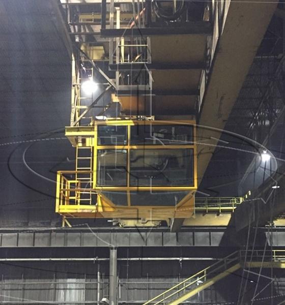
Recently, Engineered Lifting Systems was asked to design and supply a small 5-ton jib crane system to a steel mill for scrap magnet cleanout application. These pit cleanout applications can get really nasty for heat and dust, so although the unit is not being run 24/7, when they do need it, it has to work, and maintenance must be a minimum.
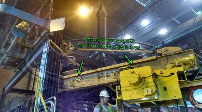
This application required a shorter span, and could only provide just over 6 feet of trolley travel, which meant the trolley would be at or near the mechanical trolley stops on a regular basis. Seeing that, we knew we wanted to protect the trolley wheels, and the jib beam to prevent issues such as the photo above.
Some general information on the equipment selected:
Hoist:
- Yale FEW frame
- 2-part double reeved, with ½” diameter wire rope
- No mechanical load brake
- Avtron 1024 PPR encoder
- Anti-Spooling bar limit for cable
Jib:
- Gorbel Model WB100MD
Crane Controls:
- Hoist: Magnetek VG+ Series 4
- Trolley: Magnetek G+ Series 4
- Jib: Magnetek G+ Series 4
Magnet Control:
- Magnetek DMC Control
The method selected for trolley travel protection for this application was 40mm 110 VAC proximity switches, using adjustable “targets” on the jib crane.
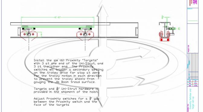
NOTE: In a high ferrous environment keep the switches mounted so that the majority of dust falls off the switches and targets as shown.
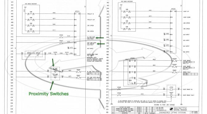
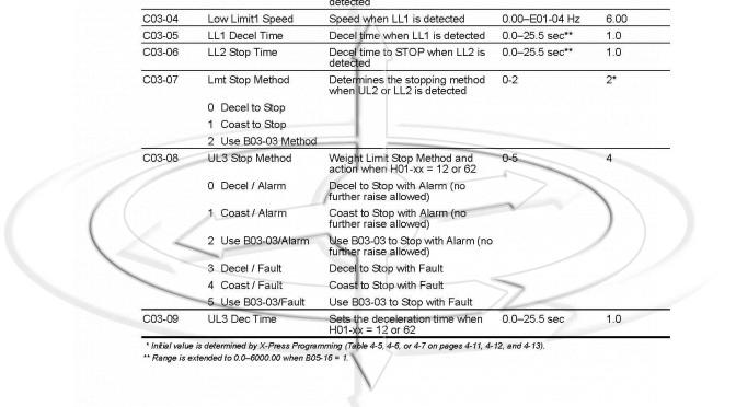
Even though they are 110 VAC switches, I still like a separate circuit for the proximity switches using ice cube relays. The S5 and S6 terminals on the S4IF input card for the drive were assigned to “End of Travel Limits” parameter code C03-07, with a value of “1” (coast to stop).
The end result provides the trolley motion to coast into the trolley stops using the adjustable targets, and as long as the proximity switch is in front of the target, the operator cannot attempt to operate the trolley spinning the wheels on the beam, in either direction.
The application of trolley limits does not need to be applied to all cranes, or all jib cranes. If the plant operations require the trolley (or bridge) to operate near the mechanical stops, you should think about the benefits of travel limits. The gouging seen in the first photo can in some cases prevent the trolley from moving, and at the worst require replacement of a structural section.
If you have any questions on this, or any of the technical bulletins please contact Engineered Lifting Systems.
Eric Brown, AKA your “Crane Doctor”
Recent news posts
Gravity Latch with Rotation Lock
Magnetek Series 3 Drives Using “Motor 2” Option
Magnetek Brake Circuit Fusing
Crane Cab Replacement Improves Function