Magnetek Brake Circuit Fusing
I thought I would share a practice that we at Engineered Lifting Systems use when ordering or reviewing a complete Magnetek variable frequency drive panel or motion control.
There are many options for a Magnetek variable frequency panel, and many of those are shown on the standardized items sheets. One of the items that you want to make sure and specify are fuses for the brake circuit. See the below illustration:
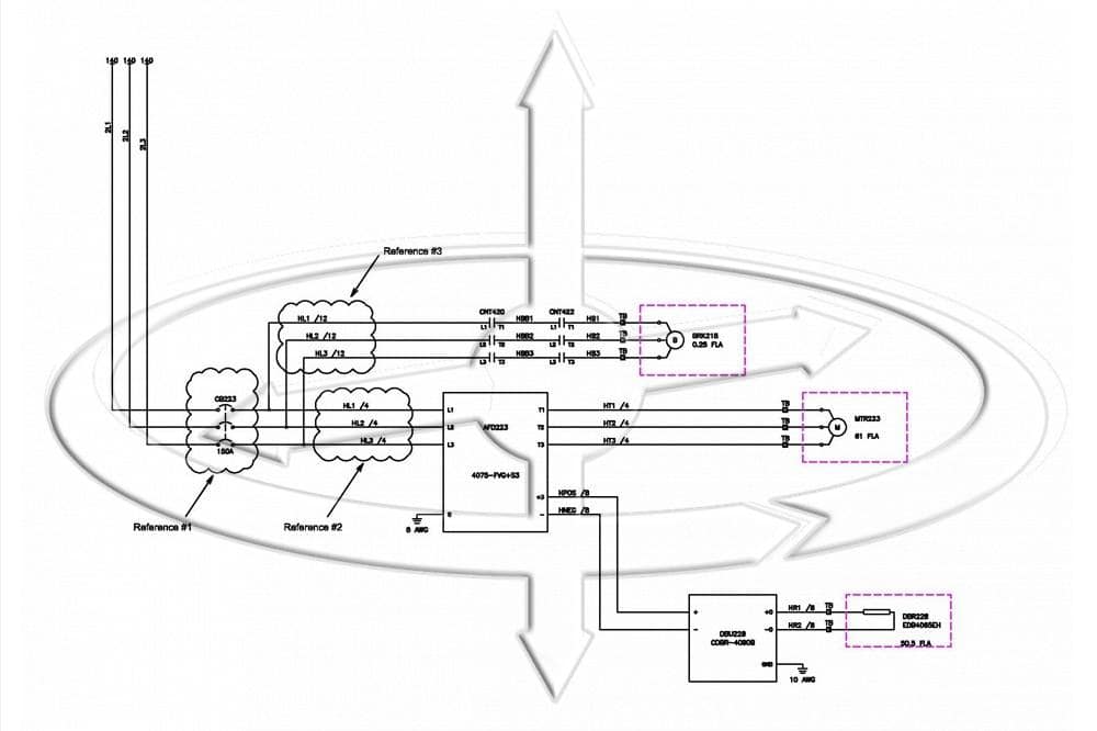
Typical Hoist Drive Power Circuit.
This is a fairly typical variable frequency drive arrangement for a 50 hp squirrel cage motor operating on 480-3-60 power, 61 full load amps.
Reference #1 shows the line side of the control, with a 150 amp circuit breaker feeding the drive. The circuit breaker is sized per NEC. In this case for a circuit breaker, maximum is 250% of full motor amps.
Reference #2 shows the corresponding wire size running from the circuit breaker to the drive, in this case a 4 gage wire.
Reference #3 shows the wire size running to the brake circuit, a #12 AWG which is fine based on the brake circuit being 480 power also. The hoist brake circuit correctly shows two brake contactors.
The problem here is that in the event of a short or ground in the brake circuit all of the #12 AWG wires will have 480 power until the 150 amp circuit breaker blows. One sharp edge while pulling wires, or a bad connection at the brake is all it takes.
This can lead to the wires in conduit, festoon conductors and motor leads to melt and cause damage to other adjacent wires. If the controls are mounted on the front girder it can be a mess to straighten out.
The correction is to specify fuses correctly sized on the line side of the brake contactors (see the below illustration).
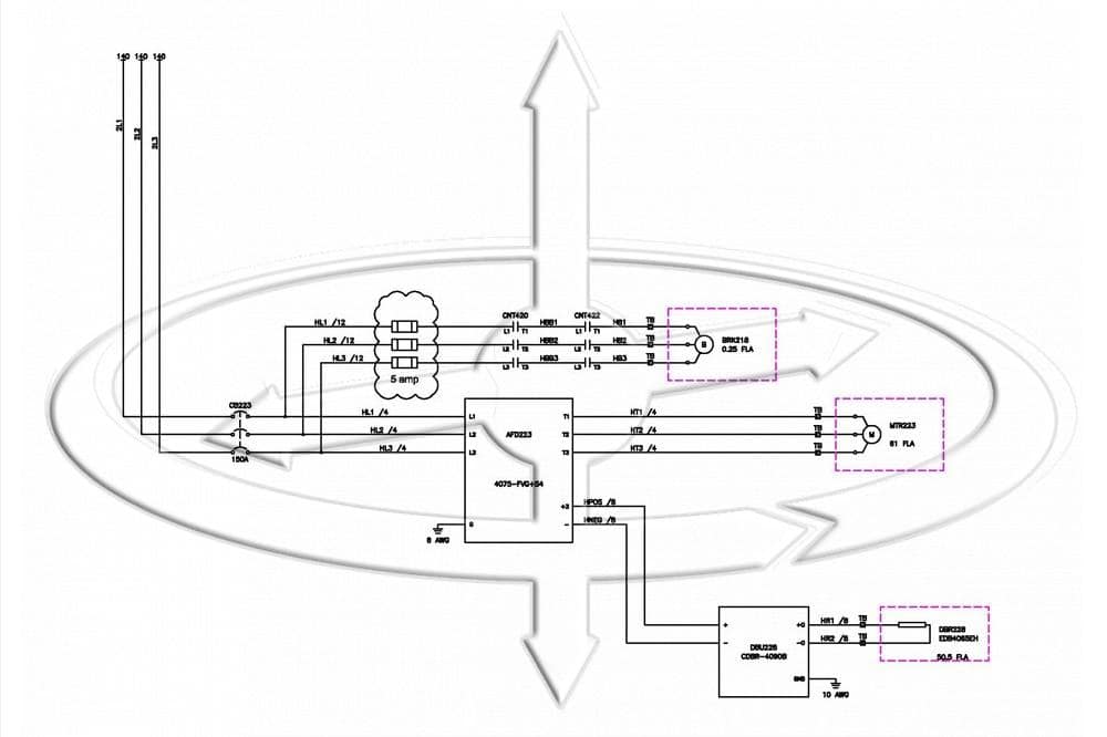
Drive with Fuses in the Brake Circuit.
On small drive applications for fractional horsepower trolley or bridge drives this may not be a problem. But these fuses are a cheap insurance against a pinched wire or stripped insulation when the bridge wiring was performed, and trouble shooting becomes much easier.
NEC Article 240.21 refers to this issue, where without overcurrent protection the length of the “taps” affects the size of the wire used. But there are limits to the length of wire, and on many cranes this maximum length would easily be exceeded when taking into consideration the festoon conductors.
If you have any questions on this post, please write to me directly Engineered Lifting Systems Contact Eric
Recent news posts
This is a sample blog post title.![Featured Image]()
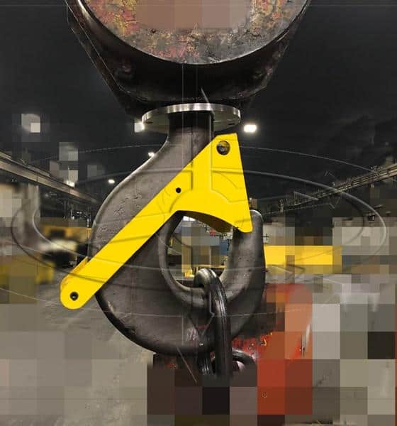
Gravity Latch with Rotation Lock
This is a sample blog post title.![Featured Image]()
Magnetek Series 3 Drives Using “Motor 2” Option
This is a sample blog post title.![Featured Image]()
Magnetek Brake Circuit Fusing
This is a sample blog post title.![Featured Image]()
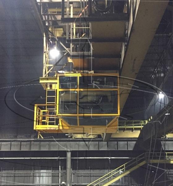
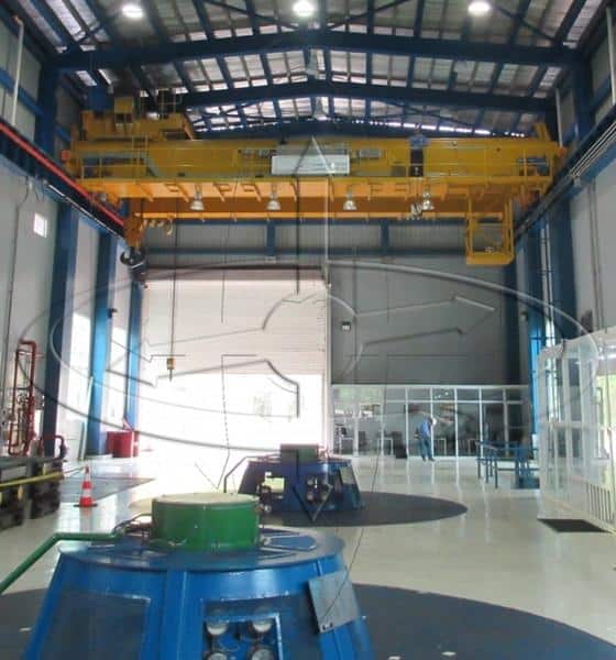
Crane Cab Replacement Improves Function
This is a sample blog post title.![Featured Image]()