Runway Electrification Isolation Sections I …
Runway Electrification Isolation Sections Improves Production and Provides Safety
Runway Electrification Isolation Sections Improves Production and Provides Safety
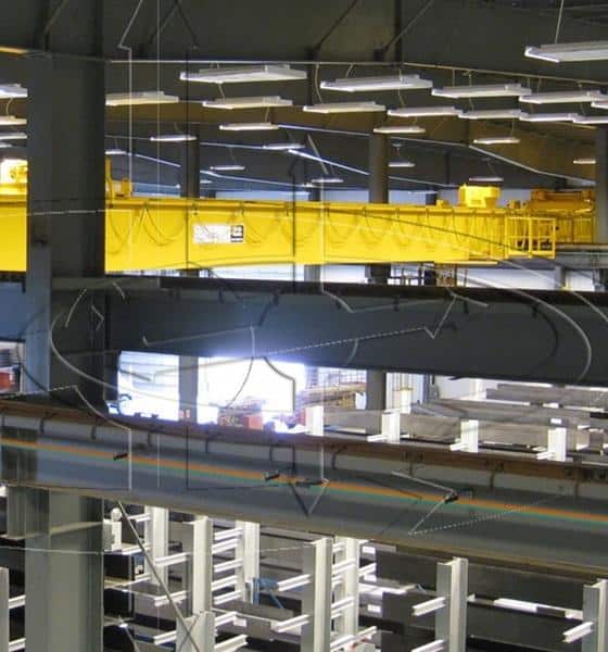
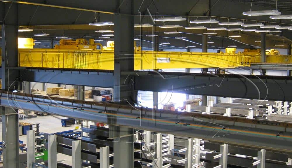
It is not unusual to have multiple overhead cranes on the same runway. While maintaining and repairing these cranes, having a system that allows a partial or segmented shut down of power within a runway section for one or more cranes is a valuable option.
Safety for maintenance personnel is paramount, but production sometimes can hamper the ability to either repair or inspect an overhead crane due to the proximity of the runway conductors. In short, you want to turn off the power to a specific overhead crane, but use other cranes on the runway.
What you are looking for is an electrification system that has one or more isolation sections. Done properly, this allows operation of one or more cranes on a runway while a crane is parked in its maintenance position on the runway.
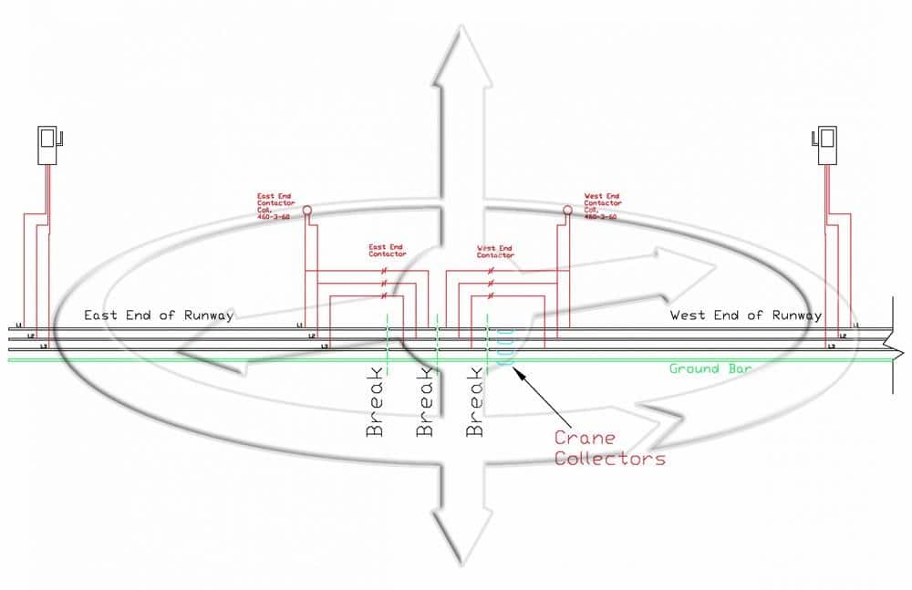
Basic illustration of a runway mainline electrification isolation system.
The above drawing shows one way to wire/connect a runway system so that one end (East or West) can be removed from service so the overhead crane can be removed from mainline power as needed.
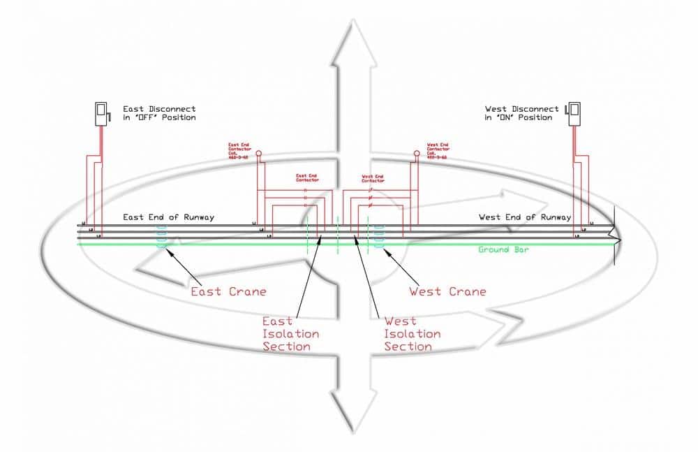
Operation of isolation section.
This second drawing shows the isolation section as it would be used to remove mainline power from the “East” end of the runway. Once the East disconnect switch has been locked out, the power is removed from the East end of the runway and the East End Contactor Coil. The East end contactor is then open removing mainline power from the East Isolation section.
Generally, an isolating section for a conductor bar system is around 1” long and made from a non-conductive product such as vinyl or plastic that couples the adjoining conductor bar. A small 1” air gap can sometimes also be used depending on the manufacturer’s recommendations for that specific style of conductor system.
This brings us to why there are two short sections of isolation for each section of runway you want to isolate. Collector shoes can be 3-6 inches in length, and with the West crane traveling east, at the first break it would potentially be able to transfer mainline power to the first isolation section.
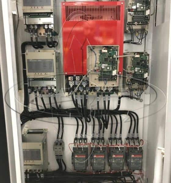
Most modern cranes today have multiple collector shoes for each phase of mainline power so we must allow for those also. See picture below:
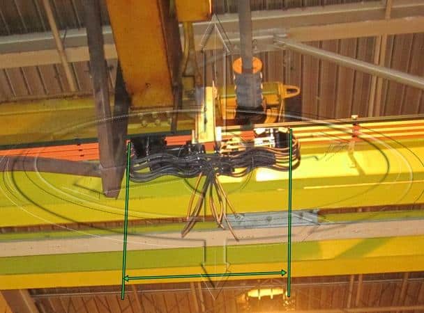
NOTE: The two center isolation sections must be a greater length than the outside dimensions shown in the above picture to prevent power being transmitted to intended dead sections.
Multiple isolation sections (also referred to as hospital or maintenance sections) can be used on a single runway. Lights that indicate when there is no power or when there is power can also be used to give a visual notice to everyone.
Just remember to:
1. Lock it out
2. Tag it out
3. Try it out
If you have any questions on this post, please write to me directly Engineered Lifting Systems Contact
Recent news posts
Gravity Latch with Rotation Lock
Magnetek Series 3 Drives Using “Motor 2” Option
Magnetek Brake Circuit Fusing
Crane Cab Replacement Improves Function