This bulletin is generated as reference and guide to anyone who is using or going to use encoder feedback on an overhead crane in order to select the correct type of encoder cable. Since a majority of applications for encoder usage on an overhead crane are on the hoist motion, this article focuses on that specific application, although much of the below is relative to any crane application, or an application in general.
An encoder on a motor when used with a variable frequency drive is to give the drive a reference (to see where the motor shaft is in rotation). The encoder uses a low voltage signal to communicate the digital signal to the drive. On Magnetek drives this is typically 12 VDC, but other low DC voltages can be used. The digital signal is handled by 3 pairs of wires and is shown below as standard:
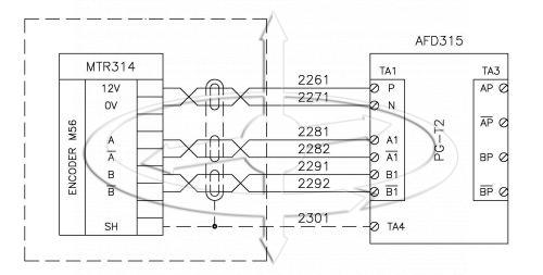
12 VDC and OV are power to the encoder, with “A” – “A Not”, and “B” – “B Not” are signal wires carrying the digital signal back to the drive (shown as AFD315).
Selecting an encoder cable that is designed to handle this power and communication is very important to ensuring a dependable communication between the drive and the encoder. The pairs of wires are twisted inside the cable itself so the cable is referred to as “3-pair twisted cable”. Twisting the pairs of wires helps to reduce noise pickup from outside sources and crosstalk on multi-pair cables.
Cross section of quality encoder cable for use on a crane and hoist is below:
1 – Outside shielding for the cable
2 – Inside shielding (each twisted pair is shielded individually)
3 – Drain wire (there is a drain wire for each twisted pair)
4 – First pair twisted
5 – Second pair twisted
6 – Third pair twisted
Cable as shown above offers the maximum protection possible to keep outside interference from disrupting communication. This cable also has a flexible construction that makes it well suited for use in a festoon system. Since you want to run the encoder cable without splices it is important to take all of the requirements into consideration when selecting the encoder cable you will use.
There are a couple of installation tips that will save you a ton of headaches.
1. Run any encoder cable in its own conduit. Do not run it with brake, control, or power wires!
2. Use Cable “Stand-offs” on your festoon to place the encoder cable some inches away from the other wires in the festoon (see picture below)
3. Use rubber cushioned loop clamps on your stand-offs (see picture below)
4. Combine drain wires and outside shielding as a ground at the drive. DO NOT ground these to the encoder.
5. Run “A” and “A Not” in one twisted pair, “B” and “B Not” in one twisted pair, and “12 VDC” and “0 VDC” in one twisted pair. DO NOT mix
6. DO NOT splice the encoder cable
7. Use 22 gauge minimum wire
8. Do not run the encoder cable over 300’ long (see engineering)

Typical Encoder Cable Stand-offs.
We have been using Magnetek’s R-22/6 encoder cable (pictured above) to great success. This is a custom cable made to the standards that Magnetek sets, and we have yet to find a better product.
As always, if you have any questions just write or call.
Eric “The Crane Doctor”
866-756-1200
ebrown@engineeredlifting.com